- 您现在的位置:买卖IC网 > Sheet目录102 > NHD-C12864WM-09-FSW-FBW-3V3 (Newhaven Display Intl)LCD COG GRAPH 128X64 TRANSFL
[4]?�
� ?�
� ?�
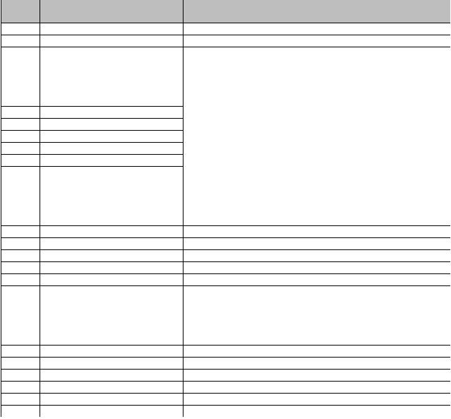
� Pin?Description?and?Wiring?Diagram?�
� Pin?No.?�
� Symbol?�
� External?�
� Connection?�
� Function?Description�
� 1?�
� CS2?�
� MPU?�
� Active?HIGH?chip?select�
� 2?�
� RESETB?�
� MPU?�
� Active?LOW?Reset?signal�
� 3?�
� RS?�
� MPU?�
� Register?select?signal.??RS=0:?Command,?RS=1:?Data?�
� 4?�
� RW?�
� MPU?�
� Read/write?select?signal.??R/W=1:?Read??R/W=0:?Write?�
� 5?�
� E?�
� MPU?�
� Operation?enable?signal.?Falling?edge?triggered.�
� 6?�
� DB0?�
� MPU??�
� Parallel?Interface?�
� DB0‐DB7:?Bi‐directional?8‐bit?data?bus?�
� ?�
� Serial?Interface:?�
� DB0‐DB5:?No?connect?in?serial?mode?�
� DB6=?Serial?clock?(CLK)?�
� DB7=?Serial?data?input?(SDA)?�
� 7?�
� DB1?�
� MPU?�
� 8?�
� DB2?�
� MPU?�
� 9?�
� DB3?�
� MPU?�
� 10?�
� DB4?�
� MPU?�
� 11?�
� DB5?�
� MPU?�
� 12?�
� DB6?�
� MPU?�
� 13?�
� DB7?�
� MPU?�
� 14?�
� VSS2?�
� Power?Supply?�
� GND?(reference?for?voltage?step‐up?circuit)�
� 15?�
� VOUT?�
� Power?Supply?�
� Connect?to?1uF?cap?to?VSS2?(PIN‐14)�
� 16?�
� CAP3‐?�
� Power?Supply?�
� Connect?to?1uF?cap?to?CAP1+?(PIN‐17)�
� 17?�
� CAP1+?�
� Power?Supply?�
� Connect?to?1uF?cap?to?CAP3‐(PIN16)?and?CAP1‐(PIN18)?�
� 18?�
� CAP1‐?�
� Power?Supply?�
� Connect?to?1uF?cap?to?CAP1+?(PIN‐17)�
� 19?�
� CAP2‐?�
� Power?Supply?�
� Connect?to?1uF?cap?to?CAP2+?(PIN‐20)�
� 20?�
� CAP2+?�
� Power?Supply?�
� Connect?to?1uF?cap?to?CAP2‐�
� (PIN‐19)�
� 21?�
� VSS?�
� Power?Supply?�
� Ground�
� 22?�
� VDD?�
� Power?Supply?�
� Power?supply?for?LCD?and?logic?(3.0V)�
� 23?�
� V1?�
� Power?Supply?�
� 1.0uF‐2.2uF?cap?to?VDD�
� 24?�
� V2?�
� Power?Supply?�
� 1.0uF‐2.2uF?cap?to?VDD�
� 25?�
� V3?�
� Power?Supply?�
� 1.0uF‐2.2uF?cap?to?VDD�
� 26?�
� V4?�
� Power?Supply?�
� 1.0uF‐2.2uF?cap?to?VDD�
� 27?�
� V5?�
� Power?Supply?�
� 1.0uF‐2.2uF?cap?to?VDD�
� 28?�
� VR?‐No?Connect�
� 29?�
� C86?�
� MPU?�
� Select?MPU?interface?pin.?C86=H:?6800;?C86=L:?8080?�
� 30?�
� PS?�
� MPU?�
� Parallel/Serial?select.??PS=?H:?Parallel;?PS=L:?Serial?�
� ?? ??�
� A??Power?Supply?�
� Power?supply?for?LED?Backlight?(+3.0V)�
� K??Power?Supply?�
� Ground?for?Backlight?�
� ?�
� Recommended?LCD?connector:?0.5mm?Pitch,?30?pin?FFC.??Molex?p/n:?52892‐3095??�
� Backlight?connector:??A2001H‐2P?????Mates?with:??A2001WR‐S‐2P??�
� ?�
�  �
�
�  �
� 发布紧急采购,3分钟左右您将得到回复。
相关PDF资料
NHD-C12864WO-B1TFH#-M
LCD COG GRAPH 128X64 TRANSFL
NHD-C12864WO-B1TGH#-M
LCD COG GRAPH 128X64 TRANSFL
NHD-C12864WO-B1TMI#-M
LCD COG GRAPH 128X64 TRANSM
NHD-C12864WO-B1TTI#-M
LCD COG GRAPH 128X64 TRANSM
NHD-C12865AR-FSW-GBW
LCD COG GRAPH 128X65 TRANSFL
NHD-C12865AZ-RN-GBW
LCD COG GRAPH 128X65 NO REFL
NHD-C12865BR-FSW-GBW
LCD COG GRAPH 128X65 WH TRANSFL
NHD-C160100AZ-RN-GBW
LCD COG GRAPH 160X100 REFLECT
相关代理商/技术参数
NHD-C12864WM-09-FSW-FBW-3V3-M
功能描述:LCD 图形显示模块和配件 FSTN (+) Transfl 62.0 x 40.0 x 5.7 RoHS:否 制造商:ELECTRONIC ASSEMBLY 产品: 分辨率:128 x 64 流体类型:FSTN Positive 接口: 背光: 背景色:White 工作温度范围:- 20 C to + 70 C 封装:Bulk
NHD-C12864WM-09-FSW-GBW-3V3
功能描述:LCD 图形显示模块和配件 128 x 64 STN-GRAY 66 x 44 x 5.7 RoHS:否 制造商:ELECTRONIC ASSEMBLY 产品: 分辨率:128 x 64 流体类型:FSTN Positive 接口: 背光: 背景色:White 工作温度范围:- 20 C to + 70 C 封装:Bulk
NHD-C12864WO-B1TFH#-M
功能描述:LCD 图形显示模块和配件 COG FSTN(+) 128x64 128 x 64 Pixels RoHS:否 制造商:ELECTRONIC ASSEMBLY 产品: 分辨率:128 x 64 流体类型:FSTN Positive 接口: 背光: 背景色:White 工作温度范围:- 20 C to + 70 C 封装:Bulk
NHD-C12864WO-B1TGH#-M
功能描述:LCD 图形显示模块和配件 COG STN+ 128x64 128 x 64 Pixels RoHS:否 制造商:ELECTRONIC ASSEMBLY 产品: 分辨率:128 x 64 流体类型:FSTN Positive 接口: 背光: 背景色:White 工作温度范围:- 20 C to + 70 C 封装:Bulk
NHD-C12864WO-B1TMI#-M
功能描述:LCD 图形显示模块和配件 COG STN-Blue 128x64 White Transmissive RoHS:否 制造商:ELECTRONIC ASSEMBLY 产品: 分辨率:128 x 64 流体类型:FSTN Positive 接口: 背光: 背景色:White 工作温度范围:- 20 C to + 70 C 封装:Bulk
NHD-C12864WO-B1TTI#-M
功能描述:LCD 图形显示模块和配件 COG FSTN(-) 128x64 White Transmissive RoHS:否 制造商:ELECTRONIC ASSEMBLY 产品: 分辨率:128 x 64 流体类型:FSTN Positive 接口: 背光: 背景色:White 工作温度范围:- 20 C to + 70 C 封装:Bulk
NHD-C12865AR-FSW-GBW
功能描述:LCD 图形显示模块和配件 STN-GRAY Transfl 59.0 x 42.0 x 5.9 RoHS:否 制造商:ELECTRONIC ASSEMBLY 产品: 分辨率:128 x 64 流体类型:FSTN Positive 接口: 背光: 背景色:White 工作温度范围:- 20 C to + 70 C 封装:Bulk
NHD-C12865AZ-FSW-GBW
功能描述:LCD 图形显示模块和配件 STN-GRAY Transfl 59.0 x 42.0 x 5.9 RoHS:否 制造商:ELECTRONIC ASSEMBLY 产品: 分辨率:128 x 64 流体类型:FSTN Positive 接口: 背光: 背景色:White 工作温度范围:- 20 C to + 70 C 封装:Bulk